[STM32F3] Hello World with STM32F3 Discovery - Part 4
Open loop Boost Converter to Close loop Boost Converter
As what we have discussed and talked about in part 3 of this blog series, we are now going to have an open loop controller first before we can properly set our PI Close loop Control System. With our duty cycle percentage value and the voltage output due to that duty cycle percentage we can then use System Identification Toolbox of Matlab to get the transfer function of the design under test. However we still need Instrument Control Toolbox to be able to bring the snapshot of our oscilloscope to Matlab.
Open Loop Boost Converter
 |
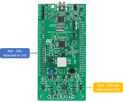
| Fig. 1 Connections for the Open Loop |
 |
| Fig. 2 Open Loop Model |
 |
| Fig. 3 Step Response to 50% duty cycle and Boost Converter Output |
Bringing in the Oscilloscope Data to Matlab
Though in my setup today I am using an LEGACY hardware, it is still acceptable in my experience. I have a Tektronix TDS 2022 and an Agilent GPIB Cable. The GPIB Cable will be used as a link to the oscilloscope and to my Desktop/Laptop (Matlab). I will be using Instrument Control Toolbox from Matlab to be able to link and command the oscilloscope to feed the data to my Matlab Software.
 |
| Fig 4. Instrument Control Toolbox - Test and Measurement Tool |
I have made a scrip out of it to let me visualize the data and do some preprocessing. The time on the waveform is form - 0.0125 to 0.0125
 |
| Fig. 5 Stem plot of the duty cycle (DAC) and voltage output |
Plant Identification
We can then use the PID tuner APP of Matlab, we can be able to find this APP on the tab above the Matlab Sofware.
 |
| Fig. 6 Plant Identification |
After exporting the plant to our workspace the result will be something like this:
Plant2 =
Process model with transfer function:
Kp
G(s) = ----------
1+Tp1*s
Kp = 0.20063
Tp1 = 0.00017044
Parameterization:
'P1'
Number of free coefficients: 2
Use "getpvec", "getcov" for parameters and their uncertainties.
Status:
Estimated using PROCEST on time domain data.
Fit to estimation data: 92.91%
FPE: 0.115, MSE: 0.1148
Since we already know the Trans Function of your plant we can then use it with simulink.
 |
| Fig. 7 Simulation Model of the Boost Converter (Transfer Function) |
PID Control
Since we already have our Transfer Function in simulink and as expected the output of our Transfer Function is similar to our real hardware. We can now proceed with the PID tuning. We should take note that I will be putting the PI controller algorithm on the sys clock cycle and not on the Repetition Update to make it more simplier. We can probably further improve it later however I wanted you to learn first on the basic workflow.
Your simulation model will then somehow look like this:
 |
| Fig.8 Close Loop Simulation Model |
Implementation
Since we have now have a Tuned PID Block with some corresponding conenctions, we can then copy this blocks except the Transfer Function of our plant. (THE PLANT IS OUR HARDWARE)
There should be some considerations of the values during implementation since tuning the PID was using values that we can directly understand. Example would be that we only used 3.3 Volts as input to our PID block however this is not the case during implementation and also our ADC feedback should also be consider to convert the values from the sense resistor (Voltage Divider) to 12 bits and then convert to 0 - 10 or 30 volts (depends on the objective).
Take note again that the PID block is running on the System Clock which is running on 0.001 secs however it should be placed on the Repetition Update (0.000128 secs). It is not a straight forward implementation since the PID block has some parameters and configurations to be set. We will talk about it in the next release.
 |
| Fig. 9 Close Loop Implamentation |
Output on the oscilloscope
 |
| Fig. 10 Close Loop Output - Oscilloscope |


Comments
Post a Comment